OMAP3 LVDS
Скопировано с LVDS on Rev B Beagleboard — Beagle Board | Группы Google
Hello,
I thought I’d share a little hack I put together back at the end of September for a Rev B Beagleboard, in case anyone’s interested. I hadn’t got round to uploading the pictures at the time (and forgot since then) but I think LVDS-on-Beagleboard will get get more topical again this month with the release of the excellent RevC update with the OMAP3 LCD outputs available.
So…
The aim of the project was to drive an LVDS TFT panel directly from the Beagleboard, *without* first going to DVI, then externally converting to LVDS (IMHO icky). The LCD panel was an AUO B089AW01, which is the 1024x600 18-bit colour TFT featured on several of the netbooks available (e.g. Acer Aspire One).
General plan:
- Remove TFP410 DVI serialiser.
- Use buffers to step the 1.8V OMAP3 LCD outputs up to 3.3V.
- Use a NatSemi DS90C363 LVDS serialiser to drive three LVDS pairs (plus one clock) to the TFT panel.
Total cost: about 10UKP of parts (3xSN74AVC8T245 octal buffers (dual power rails), 1xDS90C363, misc connectors/passives) plus a small PCB (homemade in kitchen with Iron-On™ toner transfer technology) plus time. (A lot of time. You’ll see the soldering below; it was enormously enormously time-consuming.)
So, it’s not pretty but it works, as the saying goes…. >:-) Anyone want to see?
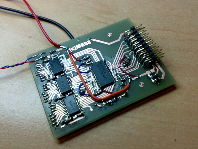
Here’s the board:
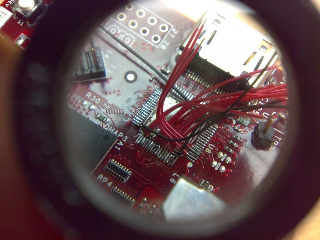
Here’s the space once occupied by the TFP410, with 33 gauge wirewrap wires being soldered on (apologies for the crappy picture quality). The flux is making it look a little messy, but it cleaned up.
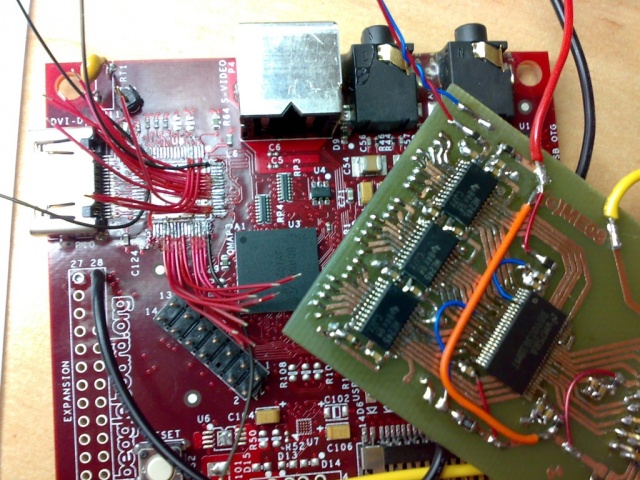
The umbilical wires in place:
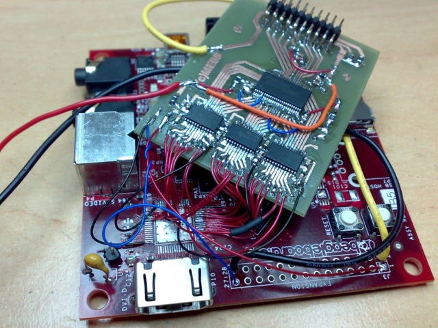
Finally, the two welded together:
Naturally I forgot to take a final shot before it got whisked away abroad (d’oh! :)), but it worked splendidly. I believe the prototype photos of a certain OMAP3-based device announced this week are it in action…..
Am looking forward to (I think Keith Williams’s) revC daughterboard. One thing to note is that most LCDs will require a lot of current on the 3.3V rail and will require an extra 3.3V power supply/regulator from the BB’s 5V supply; software side of things was easy, and it was a lot of fun. :) Hope that is of some interest, Matt


